|
This Winchester Model 94 disassembly tutorial is not a to-the-last-nut-and-bolt procedure. Rather, it takes a Model 94 down to its major assemblies using tools a normal reloader/gun tinkerer would have on hand. Those assemblies, however, can be disassembled by the brave (and the foolhardy) with the aid of a set of roll pin punches and very little else. However, I strongly suggest leaving disassembly of those assemblies to the hands of a good gunsmith.
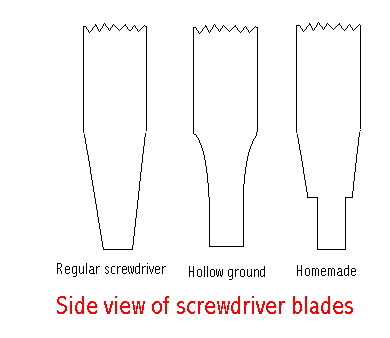
Many shooting/reloading supply companies sell sets of hollow-ground gunsmith screwdrivers or bits. I use a Lyman Magdriver which comes with seven hollow-ground bits in its handle. It costs about $20. Lyman won't sell just the bits so when I break a bit or need one not supplied, I buy el cheapo Wal-Mart As the graphic shows, regular screwdriver bits are wedge shaped. Use one on a firearm screw and get a boogered-up screw head. Don't say I didn't warn you. Almost all parts shown in this tutorial are available from Winchester Parts and Service (1-800-322-4626), Brownells www.brownells.com and Numrich www.e-gunparts.com.
Brownells also sells a gun-specific set of screwdriver bits:
The Brownells site offers a free, clear, exploded view diagram they call a "Schematic." Click the "Schematic" tab at the top of the main page, then follow directions. I used "94 Top Eject- S/N Above 2,700,000 Schematic ID# 351." The Numrich site offers exploded view diagrams but with a 99¢ download fee. So if Brownells doesn't sell a part or has it on backorder, I open the Brownells schematic in one browser window and the Numrich parts-listing page in another window. You'll need your rifle's serial number in order to see the proper schematic. Note: both of these sites and other sites I checked use the same Winchester terminology for each part. In other words, although each company might have a different part number for a "Finger Lever Link Pin," that name gets you the same part from each company. For the purpose of this tutorial I have listed the Brownells retail price for each part, when available. I did that easily because I saved the proper Brownells schematic web page to my computer's desktop. Offline, I can open the page and there's the schematic and the parts listing. You should do the same. An exploded view is handy when trying to put something back together. Hint hint. In Internet Explorer, in the upper left-hand corner of the window click "File." When the tab opens, click "Save As. . . ." and save the web page to your desktop or wherever. (Don't worry. The only thing actually on your desktop will be a little clickable icon.) The Model 94 shown here is circa 1976 with SN 4,537,XXX. I call it my "woods/heart attack rifle." You can read much more about it here.
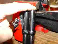
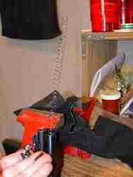
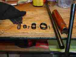
I'm pushing the plug down because the "Magazine Spring" ($7.31) is under tension. If you don't hold the plug down, parts will fly everywhere when the spring pops out. That's the "Magazine Spring" sticking out of the "Magazine Tube" ($24.30) and that's the plug and screw in my hand. Remove the spring, then point the end of the tube down and the "Magazine Follower" ($5.35) should fall out. It's a thimble-like device which rides up and down the Magazine Tube on top of the last cartridge in the magazine. If the follower doesn't fall out, open the bolt, stick your finger in the action, then give the end of the follower a little push. Now we loosen the "Front Band" ($15.50) by removing the "Band Screw, Front" ($1.79).
Yes, that Magdriver bit is too small.
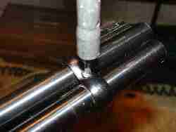
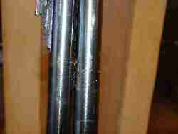
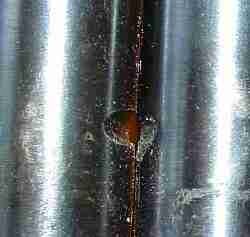
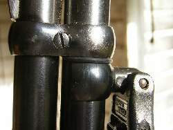
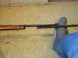
This photo shows the notches in the barrel and in the Magazine Tube. The Front Band Screw passes through the notches and, basically, prevents the Magazine Tube from falling out of the rifle. It shows wear on the rear portion caused by the barrel moving backward under recoil while Newton's First Law of Motion kept the tube at rest. This close up shows the wear on the tube. I alleviate the wear by snugging an Uncle Mike's sling swivel barrel band against the Front Band rear side. It absorbs most of the recoil, preventing further wear. A couple of years after the above photo was taken I discovered a better way to handle recoil wear on both the barrel and the front band. I took the mag tube to the local NAPA store and bought an o-ring to fit. (NAPA # 727-2015 o-ring) By snugging the o-ring between the front band and the mag tube band it stopped the wear problem. If you like a free-floating mag tube for better accuracy, install an o-ring or face excessive wear. Next we loosen the "Rear Band, Carbine" ($15.50) by removing the "Band Screw, Rear." The Magazine Tube will now slide forward out of the "Forearm, Standard, Walnut" ($38.23). If it doesn't, wiggle it until it's free.
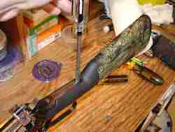
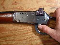
We begin by removing the "Tang Screw" ($5.03) and then removing the stock. The screw out, wiggle the stock and pull rearward at the same time. You might have to give it a knock with your knuckles. You might even have to wiggle, pull, knock, and twist. But it should come off without much trouble. The Tang Screw is the only screw holding it.
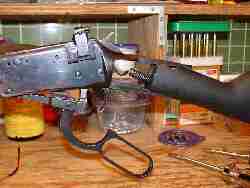
Take note of the coil mainspring trigger/tang assembly on this rifle SN 4,537,XXX. All the Model 94 parts lists I've read clearly state that flat mainspring trigger/tang assemblies are used on rifles SN 4,580,000 and below. Here we see more evidence of the shadetree gunsmith who once worked on this rifle. He probably had the coil mainspring assembly on a junker rifle and put it on this rifle—at the new price, I would bet.
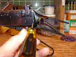
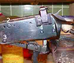
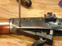
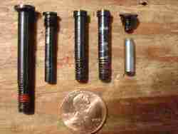
Put the hammer at half-cock. Then out comes the "Link/Hammer Screw." Known here as #1 or the hammer screw. With the screw out and the hammer still on half-cock, wiggle the trigger/tang assembly while pulling down. It's a tight fit against the walls of the receiver, but it will eventually come out. When it does, set it aside. Now we remove the "Finger Lever Pin Stop Screw." Known here as #2 or the finger lever pin stop screw. Be careful. It's a short little fellow and easy to lose.
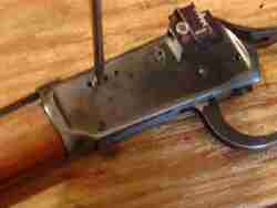
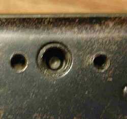
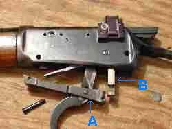
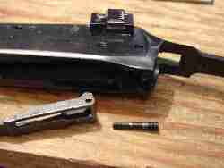
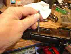 Ok. The bolt is closed. The "Finger Lever Pin" is centered in the hole. We now turn over the rifle, take a small punch, stick it in the little hole provided, and we knock out the "Finger Lever Pin." (I shouldn't tell this on myself, but I used to think the tiny hole was for oil.)
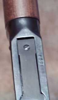
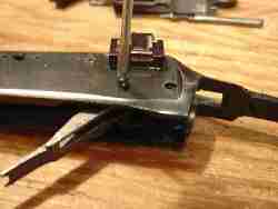
You probably won't need a hammer; I didn't. I just pushed with my hand on the punch, and out popped the pin. A nail would probably work as a punch. Now, turn the rifle over and open the bolt. It's time to remove screw #3, better known in parts lists as the "Link/Hammer Screw." It's known here as #3 or the link screw. If your rifle is above SN 6,000,000 or so, you'll have a link pin instead of a link screw, and the pin will be held in the link by this small screw. Remove it, and knock out the pin.
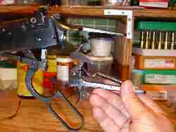
This photo added 1-26-2006 and is Copyright 2006 by Steve Barrett. The link screw out, the rifle will now fall apart.
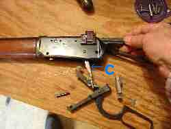
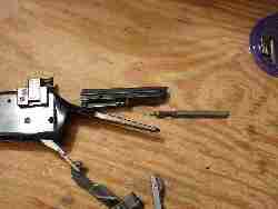
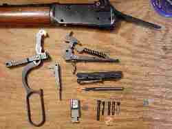
The link/lever and locking bolt assemblies out of the rifle, pull the "Carrier" C down. Now grasp the "Breech Bolt" and pull it rearward and out of the rifle. Turn the "Breech Bolt" upside down, and out falls the firing pin—"Firing Pin" ($18.00) The last screw—#4, the "Carrier Screw" ($2.59). Here it is. The "Carrier" on the left, the "Carrier Screw" on the right. If you'll notice in the full size photo, this "Carrier Screw" is worn. It's on my replace list.
If you'll notice, one of the link/hammer screws is worn. It's also on my replace list.
If you take your older Model 94 down as far as I took mine for this tutorial, you will probably discover, as I did, lots of crud and some worn but easily replaceable parts. My woods rifle's trigger had creep and seemed to operate in stages. I did not disassemble the trigger/tang assembly, but I did give it a thorough cleaning with oil, rags, and Q-tips®. Result = good trigger now. But if you take a rifle apart, you've got to put it back together. You don't want to walk into a gunsmith's shop and hand him a sack of parts and say, "Would you please put this Model 94 back together for me?" To put it back together, we reverse the take it apart process:
by making your online purchases through our sponsor links. Click here.
|
 The goal of this tutorial is to teach the reader how to disassemble a Model 94 in order to make minor repairs or perform major cleaning. Tools needed are (1) a small punch, and (2) a set of hollow-ground screwdrivers.